Our Mission

We aspire to set a benchmark in the industry with our quality products and bring value in the lives of our Customers, Investors, Partners and Employees.

Contact Us

  • 022 25034848 / 25034747
  • sales@kentercables.com
  • 68, Sidhpura Industrial Estate, Masrani Lane, Kurla, Mumbai - 400070
 ISO certification
9001:2015
Follow Us:
Top

Co – Axial Cables

Kenter Cables / Our Products / Co – Axial Cables

Description

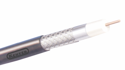
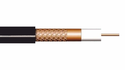
KENTER Co-Axial Cable is extensively used by leading cable TV companies, surveillance systems installed in areas such as banks, airports, industrial plants, military installations, etc. The central conductor is of solid bare electrolytic graded copper which is 99.97% pure. The name Co-Axial is given as ‘Co’ means ‘Two’ conductors on the same axis. The first conductor is the center copper conductor and the second conductor is provided in form of a metal braid over the insulation over center conductor. At high frequency, the current flows through the skin effect thus copper coated steel wire or copper-coated aluminium wires are also used sometimes. Co-Axial Cables are mainly used for carrying Radio, Audio and Video signals. They act as the lifeline of CATV Network having very low signal loss with an impedance of less than 75 ohms. Aluminium Alloy Wire braiding and aluminium foil are used as shielding from outside interference from motors, fluorescent lights, nearby computers, etc. The outer jacket is of a special UV-resistant PVC compound.

Type

Available in specified RG & UR series as per MIL-C-17 / BS:2316 / IS:5608 / IS : 11967

Sizes

Suitable for Impedance of 50 / 75 / 100 / 125 ohms

Options

Conductor : Plain / tinned / copper clad steel / Sliver Plated

Insulation : Solid / Foam / Semi air spaced

Screen : Single / Doubled braid

Sheath : PVC / HR PVC / FRLS / P.E.

Construction

Cable Type

Parameters

RG 59

RG 6

RG 11

Center Conductor

Solid bare Copper

Solid bare Copper

Solid bare Copper

Nominal Diameter of Conductor

0.81 mm

1.02 mm

1.63 mm

Dielectric (Insulation)

Foam PE

Foam PE

Foam PE

Diameter over Insulation

3.70 mm

4.60 mm

7.10 mm

Outer Conductor 

1st Shield

2nd Shield

Al-foil

Al-alloy braiding

min 60% coverage

Al-foil

Al-alloy braiding

min 60% coverage

Al-foil

Al-alloy braiding

min 60% coverage

PVC Sheath thickness

0.90 mm

0.90 mm

0.90 mm

Overall Diameter

6.30 mm

7.30 mm

10.30 mm

Electrical Parameters max. resistance of center in Ohm/100 mtr at 20° C

3.50

2.14

0.85

Nom. Capacitance PF/mtr

53

53

53

Characteristic Impedance (Ohm)

75

75

75

Nom. Velocity Radio

85

85

85

Attenuation @ 20 C DB/100 mtr at

5 Mhz

4.02

1.95

1.25

55 Mhz

6.80

5.20

3.15

211 Mhz

13.00

9.50

6.23

250 Mhz

14.0

10.50

6.72

300 Mhz

15.60

11.50

7.38

350 Mhz

16.40

12.45

7.94

400 Mhz

18.00

13.30

8.53

450 Mhz

19.20

14.35

9.02

550 Mhz

21.30

15.70

9.97

600 Mhz

22.05

16.45

10.43

750 Mhz

25.15

18.35

11.97

870 Mhz

27.20

19.95

13.05

1000 Mhz (1 Ghz)

47.00

21.45

14.27

No Comments

Sorry, the comment form is closed at this time.